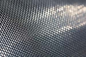
Fly Screen Mesh

PVC Coated Fibreglass Screen Mesh
Lorem ipsum dolor sit amet, consectetur adipiscing elit. Aenean egestas at magna id aliquet. Maecenas nec dictum dolor. Integer libero

Fly screen mesh has been around a very long time. Over the course of a millennium, mesh has evolved to a point where it is a true technological marvel.
Influenced by world leaders and captains of industry, it has been shaped by revolutions and refined through advancements in technology & automation to become a commodity that skillfully belies its contribution to first-world culture, health & happiness.
Lorem ipsum dolor sit amet, consectetur adipiscing elit. Aenean egestas at magna id aliquet. Maecenas nec dictum dolor. Integer libero
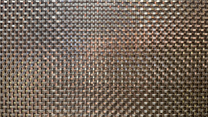
Lorem ipsum dolor sit amet, consectetur adipiscing elit. Aenean egestas at magna id aliquet. Maecenas nec dictum dolor. Integer libero
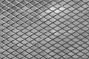
Lorem ipsum dolor sit amet, consectetur adipiscing elit. Aenean egestas at magna id aliquet. Maecenas nec dictum dolor. Integer libero
Lorem ipsum dolor sit amet, consectetur adipiscing elit. Aenean egestas at magna id aliquet. Maecenas nec dictum dolor. Integer libero

The cost of screen/mesh production is a major consideration for industrial or agricultural applications. So occasionally, screen mesh is produced
Fly Screen Mesh truly is a modern day mystery. Nobody knows exactly when it was invented, or by whom. A common misconception is that it was invented in the early 19th century, however, these reports only represent some of the earliest documented commercial applications.
Mosquito netting certainly has its origins much earlier than this. A wide variety of literature as far back as the 15th century shows us that such netting was widely used across the subcontinent and there is even some anecdotal evidence that Cleopatra slept with the aid of mosquito nets as far back as 50 BC.
As the 19th century drew to a close however we started to see a number of commercial interests appear and by the turn of the 20th century, window screens had finally gained mainstream popularity.
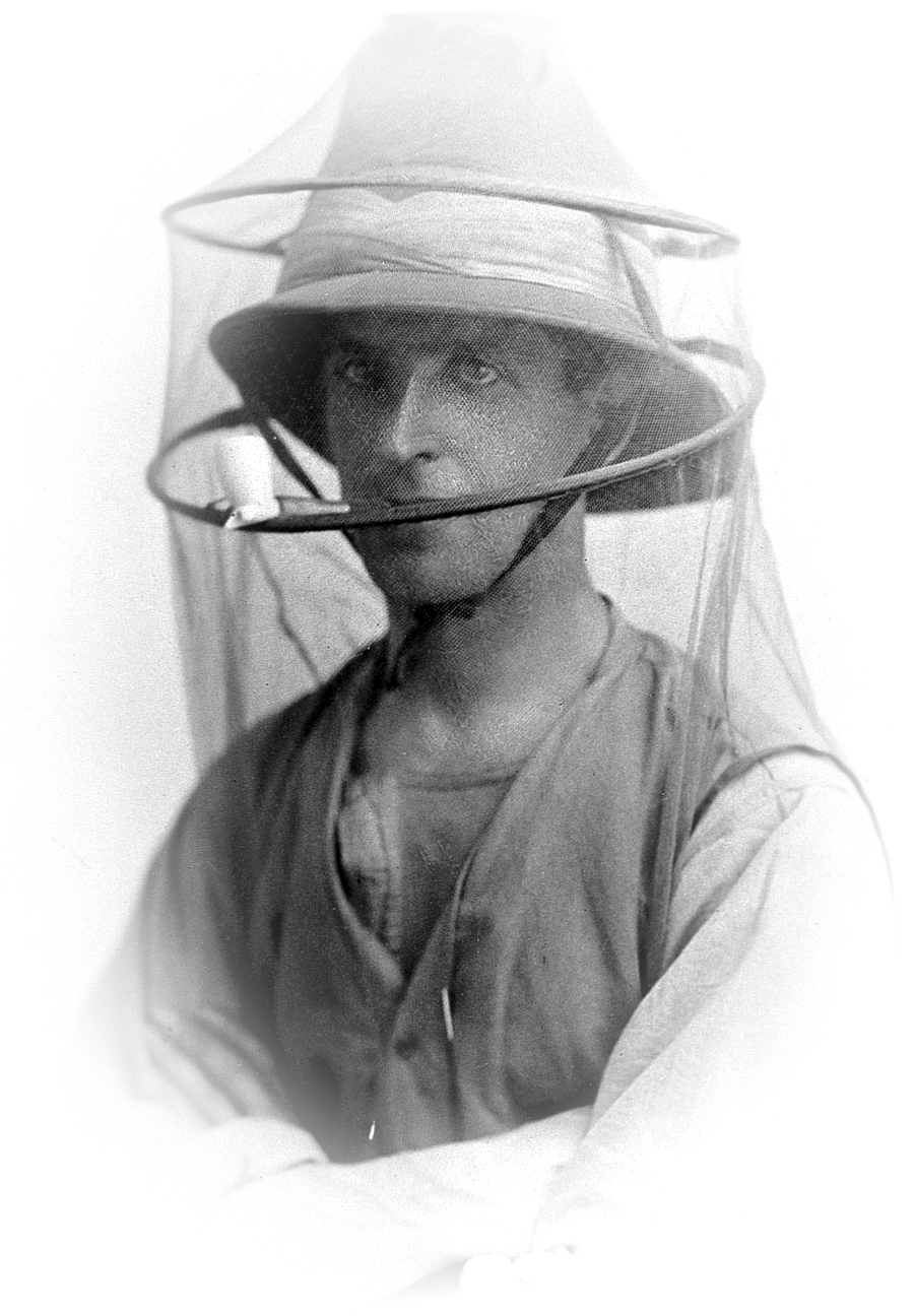
Over the last 50 years, significant scientific progress has enabled mass manufacturers to satisfy increasing consumer demand for fly screen mesh, turning this unassuming commodity into a stellar example of cutting edge manufacturing technology.
Now, it has become ubiquitous in our homes and a critical component in outdoor, adventure & lifestyle products. Here, we will take a closer look at how fly screen mesh & mosquito netting is made, the materials that are used and what options we have to choose from when considering the variety of mesh types on the market today.
One major influence on mesh manufacturing has been the constant development of new techniques through scientific and industrial advancements, including:
Over many years, these techniques have seen screen mesh production evolve, resulting in more consistent quality, finer grades of mesh allowing better airflow, greater protection against environmental elements and higher tensile strength at far lower costs.
Extrusion is a textile manufacturing process that takes a material that exists in one form, forces it through a device using heat and pressure to create a desired shape or cross-sectional profile.
In the case of fly screen mesh, this process creates the individual wires that we see in our screen. Once created, each wire can then be woven, knitted or welded together to produce a finished product.
Most commonly used with thermoplastic-based raw materials, extrusion is a very cost effective process. While this is highly desirable, these materials tend to struggle with environmental extremes such as heat & UV.
As a result, many composites and hybrid products are in existence today as manufacturers try to find the right balance between strength, durability and production cost, but we’ll address the raw materials in more detail later in this article.
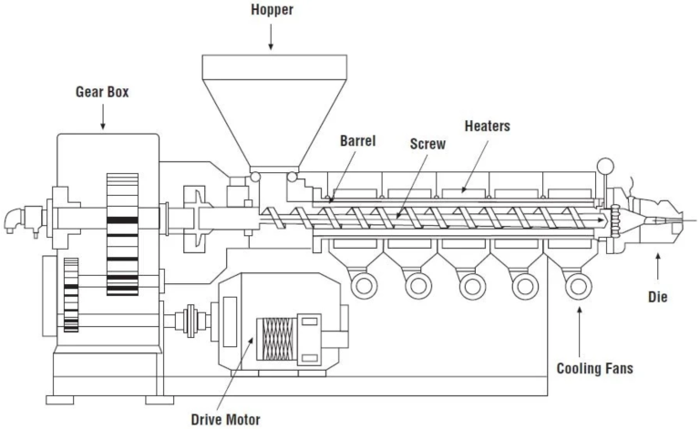
The extrusion process begins as raw materials are fed into a hopper. The hopper is a large bin, usually supplied by a gravity feed, that forces the raw materials forward into the barrel.
Hoppers usually have their own independent method of forcing raw materials into the barrel (such as a screw or billet) and depending on the formulation of the mesh fibres, it isn’t uncommon for there to be multiple hoppers delivering multiple materials at different stages of the extrusion process.
It is the job of the screw to force the materials forward, mix the materials & generate pressure inside the barrel chambers. Extruders can have one or more screws:
Single screw extruders are the most simple, cost-effective example of a versatile machine that can be easily modified to produce different strand diameters and shapes, depending on the specific requirements of the screen being made.
They produce high volumes of fibreglass or polyester at high speed (15 metres per minute or more), making them a superb choice for large-scale manufacturing operations.
The screw typically has several sections, including the feed zone, the compression zone, and the metering zone.
In the feed zone, raw materials are pushed forward and melted by friction with the screw. In the compression zone, the melted materials are compressed and mixed together to form a homogeneous melt. In the metering zone, the melt is forced through a die at a constant rate.
Twin screw extruders are more complex and provide greater flexibility and control over the extrusion process. The use of multiple chambers and screws allows for independent and simultaneous processing of materials inside the chamber. Some examples include:
As a result, they can process a wider range of materials, including those with more complex formulations and they also tend to generate less shear stress on the fibres resulting in higher overall strength, quality and consistency.
Better suited for use in the production of PVC/plastic pipes and conduit, these are not as common in mesh manufacturing due to the high cost differential.
Heat is applied to the materials while passing through the barrel using heating elements, such as electric heaters or heating oil, to maintain the temperature of the melt. The barrel may also have cooling channels to help regulate the temperature of the melt.
Temperatures are typically in excess of 200 degrees celsius, amplified by both pressure (typically north of 100,000 PSI) and friction, which melts the material making it malleable enough to travel down the die.
Not only does the barrel facilitate heating of the materials, it allows them to be mixed at precisely the right moment to produce the greatest consistency.
A little like a cup of coffee that hasn’t been stirred, the homogeneity of combined materials has a significant bearing on the quality of each mesh fibre produced.
As a result, it’s quite common for the extrusion barrel to use multiple chambers for mixing, heating and applying pressure. It’s also common to see manufacturers retro-fitting extruders with additional equipment to suit their own “recipe”.
They will tweak both their formula and the equipment to suit specific conditions allowing these extremely sensitive components to produce more consistent, reliable mesh fibres.
A die is a device that accepts our molten raw material and channels it through specially shaped apertures into its final form – long, consistent fibres or strands. These dies are actually quite varied, but when it comes to mesh production, the most common type of die used is a spinneret die. These dies typically consist of 3 components:
The distribution plate is located at the entrance to the die and is responsible for accepting our raw materials from the extruder barrel and evenly distributing them across the manifold.
The plate typically consists of a flat or slightly curved surface with a series of small channels or grooves cut into it. As the molten polymer enters the distribution plate through a central opening, it is distributed across the plate through these channels or grooves.
These channels or grooves encourage the flow to move around a series of dividers or baffles that help to create a more uniform flow of polymer across the entire surface and prevent any areas from becoming overfilled or underfilled.
The manifold is a section of the spinneret die that channels the molten polymer towards the spinneret plate. It is located downstream of the distribution plate, and effectively does the same thing as the distribution plate but in a slightly different way.
It consists of a series of channels or chambers that are connected to the distribution plate, leading to the spinneret plate. As the polymer flows through these channels or chambers, the flow rate, pressure and temperature can be controlled to ensure there are no inconsistencies in the raw material’s path to the spinneret plate.
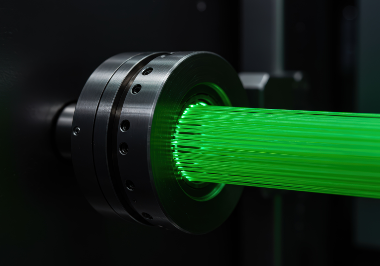
The spinneret plate is the main component of the die and contains a series of small holes or orifices through which the molten polymer is extruded. Think of it like a shower head.
The diameter of the holes can range from a few microns to several hundred microns, depending on the application and the shape of the holes can also vary, with round, elliptical, or other shapes used depending on the fibre being produced.
There are numerous other variables that affect the end result, such as:
While relatively uncommon, this technique can be used in specific applications where a combination of different materials or properties is required.
Co-extrusion is a process where multiple materials are extruded through a single die to create a multi-layered product. It may be used to add specific properties to the mesh such as UV stability, colour, or additional strength.
For example, some manufacturers may use co-extrusion to create a multi-layered mesh with a UV-stable outer layer and a stronger inner layer for added durability. This can be particularly useful in applications where the mesh will be exposed to the elements for extended periods of time.
Another example where co-extrusion may be used is in the production of security screen mesh, which is designed to provide additional strength and security for doors and windows. In this case, a multi-layered mesh may be produced with a strong, high-tensile core layer and a lower-tensile, more ductile outer layer that is resistant to cutting and puncturing.
This process requires multiple extruder barrels and screws, each with its own temperature control and melt pump to independently control the flow rate of each polymer. The design of the die is also usually more complex, as it must allow for the different polymers to be layered in a specific way to achieve the desired properties. Additionally, the use of a co-extrusion process may require more advanced control systems to ensure that the different layers are being extruded at the correct rate and thickness.
It’s worth noting that co-extrusion is a significantly more expensive process than traditional extrusion, and it is therefore rarely used in fly screen mesh applications.
In the Direct Draw Method, also known as the Direct Melt Method, there is no barrel, no screw and no die. Instead, a small furnace is used to melt the raw materials and keep them at a specific temperature until they are ready for extrusion, at which time the molten glass or polymer is fed into a nozzle, exiting in a single, perfect strand.
Overcoming the lack of a barrel and screw (as used in traditional extrusion) is achieved through greater control of temperature.
Typically, the screw controls pressure and flow rate, however, in the direct draw method, temperature is used to control viscosity, and through the use of inert gases (such as Nitrogen or Argon), positive pressure can be created inside the furnace to assist flow rate. Additionally, no die is required as the molten glass or polymer is fed directly into one or more nozzles. The nozzle is a specially designed component used to extrude the molten material into the desired shape with one important difference from a die – it can be moved along the x and y axes to create the desired pattern or shape of the fly screen mesh.
Here, the die is completely redundant as the material is formed directly out of the nozzle, and the potential for movement allows for great flexibility and precision while eliminating the need for weaving or bonding.
Nozzles are typically made of heat-resistant materials, such as ceramic or tungsten carbide.
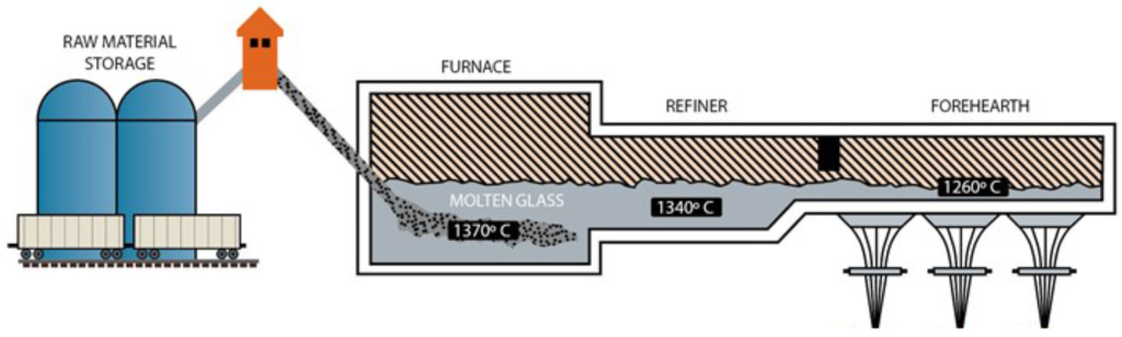
The Direct Draw Method is capable of producing fibres with a higher surface quality and more uniform diameter than the extrusion method, which leads to a higher-quality mesh.
So why is direct draw not the preferred method of fly screen mesh production? The high cost of production. For smaller production runs, costs are significantly higher and output is generally slower, which further exacerbates the cost.
This method is more popular when dealing with carbon fibres, aramid fibres, and other high-performance materials. Applications requiring high strength, stiffness, and resistance to wear and corrosion such as aerospace, defence, and sporting goods industries are ideal for this method of manufacture.
After the polymer exits the die, it is in a molten state and needs to be cooled down to solidify and maintain its shape. The materials we are typically dealing with here do not have very good thermodynamic properties which means they do not conduct (or dissipate) heat very quickly, requiring more effort to cool them than (say) metals and alloys.
In general, the most common methods for cooling and collecting melt-blown fibres include:
Once cooled and solidified, they are typically collected onto a conveyor belt or other collection device in preparation for further processing.
For the production of fly screen mesh, the collected fibres are typically laid down in a uniform layer onto a conveyor belt. These fibres then undergo a process called “orthogonal drawing”, which passes the fibres through a pair of rollers that stretch and align them in opposing directions in preparation for bonding.
Once the fibres have been correctly oriented at right angles, the two sets of fibre are bonded using heat, pressure and sometimes even sound! So far, everything leading up to this stage serves the integrity of the individual fibres. This plays a big role in burst strength, but it is relatively insignificant to tensile strength or tear strength as described below:
Instead, it has a significant impact on tensile strength by increasing the cohesion between fibres, which helps prevent fibres from separating or breaking under tension. It also improves the tear strength of the mesh by providing additional resistance to the propagation of tears along the fibres.
For these reasons, bonding plays a critical role in the ability to produce a high quality fly screen. Here are the most common methods used in the industry today:
This process is the most common method used, with a device called a calender, which consists of a series of rollers that apply heat and pressure to the fibres as they pass through the machine.
The rollers can be heated or cooled as needed to achieve the desired temperature for bonding the fibres together. The pressure applied by the rollers is also adjustable to ensure that the fibres are bonded together evenly.
One reason that calendering is favoured over other bonding methods is that it is highly efficient and cost-effective. Calendering can be done at high speeds, allowing for the production of large quantities of screen mesh in a relatively short amount of time.
It is also compatible with a wide range of polymer materials, making it a versatile choice for manufacturers.
Finally, it creates a strong, durable bond that is able to withstand the stresses and strains of use as a fly screen. The heat and pressure used in the calendering process create bonds between the fibres that are able to withstand tension and tearing, resulting in a high-quality screen mesh product.
Another device used for bonding the melt-blown fibres is a laminator. A laminator applies heat and pressure to the fibres in a similar manner to a calender but uses a different type of roller.
The rollers in a laminator have a textured surface that creates a pattern of bonding points between the fibres. This is most commonly required in specialised applications, such as a multi-layered mesh, when increased durability is required or when additional features such as UV protection or insect repellent properties are being applied.
This method involves the use of high-frequency vibrations that subsequently create heat and pressure between the fibres, causing them to bond together.
It is extremely useful for bonding materials that present challenges using traditional methods, such as very thin or delicate fabrics. It can also be used to bond dissimilar materials, such as combining a mesh layer with a non-woven layer.
It goes without saying that specialised equipment is required and the application of this technique is performed in carefully controlled environments at a much higher cost.
This process typically involves passing the bonded mesh through a series of rollers that are arranged in a specific configuration. Rollers are used to stretch the mesh in both the machine direction (MD) and cross-machine direction (CD) simultaneously while maintaining the alignment of the fibres.
This can create a more uniform and stronger mesh that is resistant to tearing and stretching.
One device commonly used in biaxial stretching is a tenter frame. A tenter frame consists of a series of clips or pins that hold the edges of the mesh as it passes through the machine. The pins are adjustable, allowing the mesh to be stretched in both the MD and CD directions.
The mesh is also heated during the process, which helps to further align the fibres and enhance the strength of the mesh.
Another device that can be used for biaxial stretching is a stenter frame. A stenter frame works in a similar manner to a tenter frame but uses a different configuration of rollers to stretch the mesh in both the MD and CD directions.
Ok, so you have your mesh fibres, can the quality of the screen still be impacted?
Absolutely! In fact, the quality of the product can vary greatly when fibre degradation occurs post-extrusion. The PH sensitivity of our raw materials, and the fact that foreign objects often have highly variable alkaline and acidic properties can cause serious damage to fine thermoplastic filaments, especially while they are cooling and hardening.
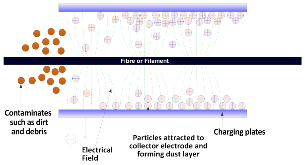
The weave itself can be compromised too, when particulate matter (such as dirt or dust) builds up to a point where it physically impedes the weave.
Modern manufacturers address this through a process called electrostatic precipitation (ESP), typically implemented after the fibres have been extruded, but before they are wound onto spools or used to produce the mesh.
ESP consists of two main components.